
Construction Drawing
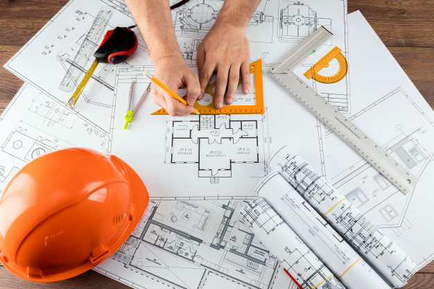
The design of a building, of whatever type, will start with pre-construction drawings that form the architectural and technical specifications. These will be used to agree the look and usage of the building. They will be used for planning permission applications and will be provided to the main contractor involved in building or modifying a building.
Career as an Architectural Technician - click here
Career as a Computer Aided Design Operative - click here
The resources we provide on this page are linked to our Mobile Construction Classroom teaching. The links to videos and existing websites are provided recognising their ownership and responsibility for the content.
Resources for Learning
Construction Drawing
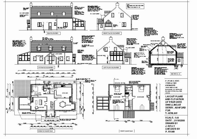
Construction drawing is a graphical representation of how a building will be built. They need to be as clear as possible and easy to read. They will include information on the specifications of materials, techniques and standards that will apply to the construction.
These drawings are increasingly done using CAD (computer aided design) technology to produce them online. A set of construction drawings will normally include:
- floor plans
- elevations of the building
- sections of the walls and floors
- specific parts of the construction which need particular attention
- window and door schedules etc
An example of a set of construction drawings is shown below for a house:
Tools
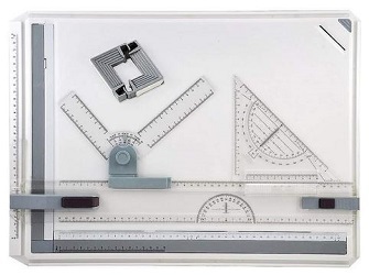
Initial designs are often started by hand, as are drawings for simple modifications to a home. This would require a:
Drawing Board - a plain flat surface which will normally include a t-shaped piece of equipment that allows lines to be drawn at 90 degree angles moving across the full board area. In addition set-squares and protractors are used to develop additional lines at different angles.
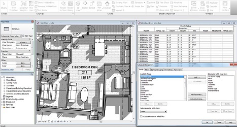
CAD systems are now being used in both small and large businesses to design online. A computer CAD system creates graphical representations of physical objects both in 2 and 3D. There is a huge range of software and systems available to the construction industry. They will often be integrated with a Building Information Model which will support the generation of quantities and cost estimates in the planning phase.
Techniques
All construction drawings will be drawn to scale so that they represent a real view of the building. A large scale drawing will show a small amount of detail but a large area eg. a floor plan or elevation. Whilst a small scale drawing will show a large amount of detail of a small area eg. a section or detail drawing.
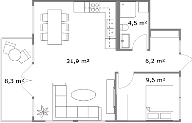
Floor Plan: these will show the layout of the internal rooms, corridors, storage, stairways etc within a building.
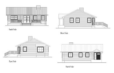
Elevations: these will show the full building from different sides and angles and will provide the dimensions and structural features.
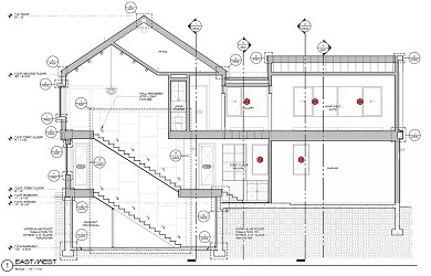
Sectional plan: these will show the size and build of external and internal walls or partitions and may show elements like beams/columns or fire safety information.
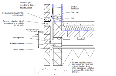
Detailed plan: these are drawings which include the detail of a specific aspect of the building and are at large scale 1:20 or 1:10. They are used for complex parts or junctions within the build.
The technical design team will be involved in producing these drawings and plans. They will include:
- engineers to design the structure
- architectural technicians to draw the detailed plans
- service engineers to design in all the services - gas, electricity, lifts etc
All will work with the architect who originally designed the building and the main contractor responsible for the construction.
Contact Us